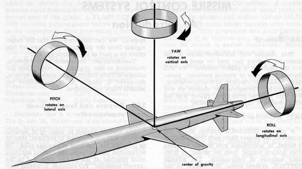
Figure 5A1.-Three control axes of a missile.
This chapter will introduce some of the numerous devices that may be used to control the flight of a guided missile. We will discuss four types of control systems: pneumatic, pneumatic-electric, hydraulic -electric, and electric. Throughout the chapter we will deal with general principles, rather than the actual design of any specific missile.
5A2. Definitions
A missile GUIDANCE system keeps the missile on the proper flight path from launcher to target, in accordance with signals received from control points, from the target, or from other sources of information. The missile CONTROL system keeps the missile in the proper flight attitude. For example, the missile axis must lie along the desired trajectory, rather than at an angle. The missile must be roll stabilized; that is, a fixed plane through the missile axis must remain parallel to a fixed reference plane outside the missile. Flight attitude stabilization is absolutely necessary if the missile is to respond properly to guidance signals. For example, assume that the missile has rolled 90 degrees clockwise from the proper attitude. Now, if it receives a "right turn" command from the guidance system, operation of the control surfaces will actually turn the missile downward, rather than to the right. But if the control system keeps the missile in the proper attitude, guidance signals will be correctly interpreted, and will produce the desired correction in the missile flight path.
To summarize: the missile control system, discussed in this chapter, is responsible for missile attitude control. The guidance system, discussed in chapter 6, is responsible for missile flight path control.
5A3. Purpose and function: basic requirements
The control system is made up of several sections that are designed to perform, insofar as possible, the functions of a human pilot. To accomplish this purpose, the control surfaces must function at the proper time and in the correct sequence. For example, in driving your car, you remember that you must make a turn at a certain distance from the starting point. You therefore anticipate the turn. In a missile control system, the remembering is done by INTEGRATING DEVICES and the anticipation is done by RATE DEVICES. These devices will be described later.
The first requirement of a control system is a means of a sensing when control operations are needed. The system must then determine what controls must be operated, and in what way. For example, the system may sense that the missile nose is pointing to left of the desired course. Obviously, right rudder is required. (Other missiles may make use of different control surfaces.) The length of time rudder control is needed depends on the size of the error. Should the attitude deviation be to one side and also either up or down, simultaneous action by rudder and elevator controls would be needed.
5A4. Factors controlled
| Figure 5A1.-Three control axes of a missile. |
YAW. Missile movement about the yaw axis is controlled by the rudder. Other methods for controlling yaw will be covered in the following section of this chapter.
ROLL. Roll deviations are controlled by differential movements of rudders, elevons, or other flight control surfaces.
5A5. Methods of control
The center view of figure 5A2 shows how the ailerons can control roll. The ailerons are attached to the trailing edges of the main lifting surfaces. When one aileron is lowered, the opposite aileron is raised. Usually, the ailerons are coupled to other surfaces in such a manner that good roll control is obtained.
The elevators are attached to a section of the tail assembly called the horizontal stabilizer. The elevators give pitch control; both elevators go up and down simultaneously.
A study of the drawings will show that control action is obtained by the control surfaces when they present opposition to air flow in such a manner that a force is produced. This force, pushing against the control surface, causes the wing or tail to which the surface is attached to move in a direction opposite to the control surface movement.
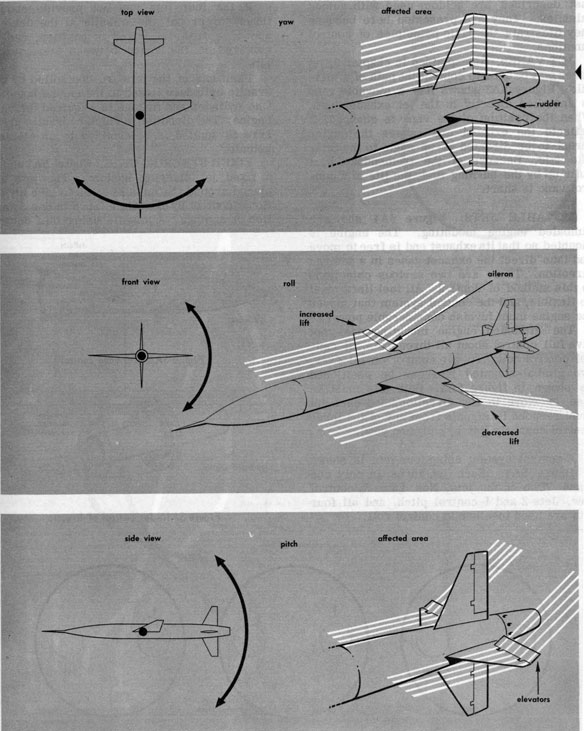 Figure 5A2.-Functions of primary control surfaces. |
| 68 | ||
| just described are seldom used with guided missiles. They are presented here because they illustrate the basic principles of control functions. | ||
JET VANES. As explained in chapter 2, jet vanes maybe used to control the path of a missile. Figure 5A3 shows how a movable vane is installed directly in the jet exhaust path. When the position of the vane is changed, it deflects the exhaust and causes the engine thrust to be directed at an angle to the missile axis. Because of the tremendous heat built up by the burning fuel, the life of a control vane is short.
MOVABLE JETS. Figure 5A4 shows a gimbaled engine mounting. The engine is mounted so that its exhaust end is free to move and thus direct the exhaust gases in a desired direction. There are two serious objections to this method of control. All fuel lines must be flexible, and the control system that moves the engine must furnish considerable power.
The gimbaled engine mounting does not give full control about all three axes. It cannot control roll. To get control on all axes, two gimbal-mounted jets can be positioned as shown in figure 5A5. Both jets must be free to move in any direction, and each jet must respond to signals from any of the three control channels (pitch, roll, and yaw).
Positions of the jets are controlled by hydraulic cylinders linked to the engine housing. One cylinder and linkage is required for each engine. The direction in which hydraulic pressure is applied is determined by an electric actuator.
FIXED STEERING JETS. Figure 5A7 shows a fixed jet steering system. The jets are placed around the missile so as to give directional control by exerting a force in one direction or another. A missile using this control
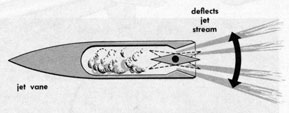
Figure 5A3.-Jet vane control
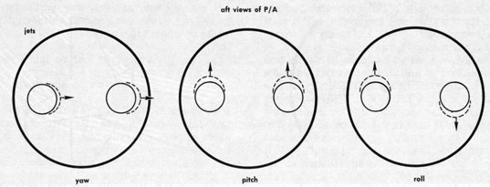 Figure 5A5.-Control by two jets. |
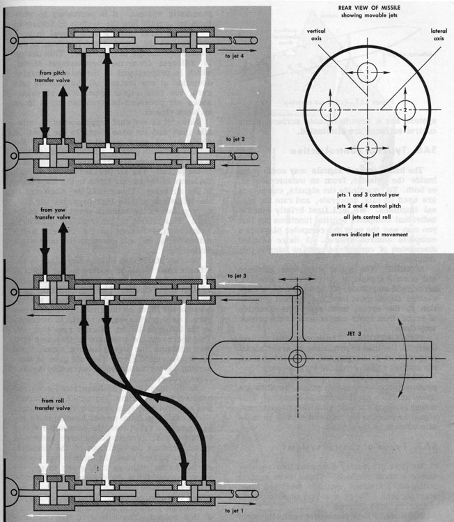 Figure 5A6.-Four movable jet control. |
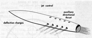
Figure 5A7.-Fixed jet steering.
system has a smooth outside surface, since control surfaces are eliminated.
5A6. Types of control action
The basic control signals may come from inside the missile, from an outside source, or both. To coordinate the signals, computers are used to mix, integrate, and rate the signal impulses. We will first briefly discuss individual computer section functions so that you may see the part the computer plays in a complete control system. A more detailed discussion of computers appears later in this chapter.
MIXERS. The mixer combines guidance and control signals in the correct proportion, sense, and amplitude. In other words, a correction signal must have the correct proportion to the error, must sense the direction of error, then apply corrections in the proper amplitude.
PROPORTIONAL. The proportional control operates the load by producing an error signal proportional to the amount of deviation from the control signal produced by a sensor.
RATE. Rate control operates the load by producing an error signal proportional to the speed at which the deviation is changing. This output is usually combined with a proportional signal to produce the desired change in missile attitude or direction.
5A7. Types of control systems
We have previously discussed four aerodynamic control methods. These were control surfaces, jet vanes, movable jets, and fixed steering jets. There are four basic methods of moving these devices.
Keep in mind that the rate signal is proportional to the speed at which a missile deviation is changing in magnitude. This change is different from the displacement signal, which is proportional to the missile angular deviation at any instant. At the azimuth rate gyro, the rate signal appears as an unbalanced air pressure between two holes in an airblock pickoff.
Now, let us see what happens when the missile yaws and its nose veers to the right. A displacement gyro signal develops at the pickoff (azimuth control air jet). The jet then pivots to increase air pressure in the left hole of the pickoff. The air pressure is fed through the lower of the two air tubes to the diaphragm of the air relay. This forces the diaphragm to the left which admits high-pressure air that, in turn, forces the azimuth servo motor to the right. This motion is then transferred through a mechanical linkage to the rudder, which moves to the left and corrects the nose-right deviation.
Another stabilizing action takes place as the missile nose veers off course to the right. A signal is produced by the azimuth rate gyro as the nose moves. The azimuth rate gyro exerts a force on the right restraining spring, because the force on the gimbal precesses the gyro. As it precesses, more air is received by the left hole of the azimuth rate pick off. This increases the pressure in the same tube that contains the high pressure signal from the displacement gyro. The rate gyro is supporting the correction being exerted by the displacement gyro.
As the missile path deviates from its desired heading, the rate signal increases the corrective action of the displacement gyro. Therefore, if the deviation from proper heading were increasing at a rapid rate, the corrective signal from the rate gyro would be large and would quickly reduce the deviation of the missile.
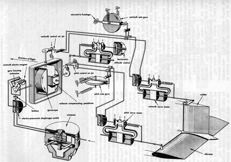 Figure 5A8.-Pnuematic control system. |
| 72 | ||
| An instant later the heading error is decreasing as the missile begins to correct its heading. The error from the displacement gyro still shows greatest pressure from the left hole of the azimuth pickoff because the heading error is still to the right. However, the signal is decreasing and the error signal from the rate gyro has reversed direction. The missile nose is now moving to the left. This puts a force on the rate gyro gimbal in a direction opposite to the former force. The precessing gyro creates a pressure in the right hole of the rate pickoff which is partially counteracted by the displacement gyro signal. Figure 5A9 shows the effects of combining the rate and displacement signals. | ||
A study of this drawing will show the advantages of having a counteraction between the rate signal and the displacement signal. If the two signals were in the same direction, the rudder would be farther away from the center axis of the missile and the missile would be heading back to the desired course at a faster rate. However, the rate of return would be so rapid that the missile would swing past the correct heading in the opposite direction. The missile would then be veering off course to the left so that the control system would need correction signals for that direction.
The same kind of action is used in the displacement and rate controls in the pitch channel. The fundamental rate gyro or rate circuit output is the same for all missile flight surface control systems.
PNEUMATIC-ELECTRIC. The pneumatic control system we have just described can be combined with other systems to refine the control action. Electric signal pickoff are accurate and dependable. They can provide a signal voltage that is proportional to displacement. They have a decided advantage over pneumatic systems in transporting information over wires, instead of through tubing.
It is difficult to design a small electric motor with sufficient speed and power to actuate missile flight control surfaces. But we can combine the best features of electric and pneumatic systems as in figure 5A10. Electrical equipment is used in the front end, and operates pneumatic servos at the actuating end. A system like that in figure 5A10 is suitable for controlling a small, subsonic, short-range missile.
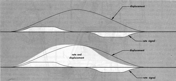 Figure 5A9.-Effect of combining rate and displacement signals. |
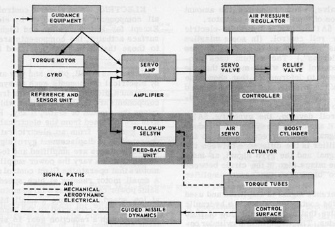 Figure 5A10.-Pneumatic-electric control systems. |
The increase in response speed is obtained by allowing air to escape, through ports, into a relief valve after the servo valve has moved a certain distance from midposition. The relief valve lets high-pressure air into the boost cylinder, which then acts in parallel with the actuator cylinder to move the flight control surfaces. The additional force provided by the boost cylinder makes it possible to obtain large control surface deflections in either direction.
The sensors for a pneumatic-electric system are electric pickoffs that detect gyro displacement and produce a voltage proportional to the heading deviation angle. This voltage is small, and must be amplified before it can operate a solenoid and air servo valve.
HYDRAULIC-ELECTRIC. This combination is similar to the pneumatic-electric, except that the actuators are moved by hydraulic fluid pressure instead of air pressure. This removes some of the disadvantages of a pneumatic system, since the fluid is not compressible.
In a hydraulic-electric system, a continuously operated pump maintains hydraulic pressure during the flight. The hydraulic fluid is circulated in a closed system, so that it can be used over and over. Thus the operating time of the hydraulic components is unlimited, and the system is suitable for long range missiles.
Variations in pitch, roll, and yaw are sensed by gyro reference units with electric pickoffs. The pickoff voltages are fed to amplifiers and computers and are then used to operate a controller. The controller is usually a hydraulic
Figure 5A11 shows a hydraulic-electric system for roll control. (In some missiles the ailerons are replaced by control devices called "rollerons".) The system uses proportional control only, which means that the controls react to information that shows the deviation of the missile axis from the desired flight path. The displacement signal is proportional to the deviation.
Should roll develop, the gyro (fig. 5A11) will detect it and cause the synchro to produce an error signal. The correction signal to the servo amplifier is the difference between the followup signal and the gyro signal, as indicated by the minus sign in the circle between the synchro block and the servo amplifier triangle.
The difference signal is amplified and used to operate the controller, which is a hydraulic transfer valve that regulates the flow of fluid to the cylinder. The piston in this cylinder operates the ailerons (rollerons; controllable jets; etc.) through mechanical linkages.
Variations in roll, pitch, and yaw are sensed by electrical components such as synchros or reluctance pickoffs. The signals from these components are fed to a computer which determines the amount of error, if any. Rate signals are obtained from the electrically driven rate gyro, or from an electric rate circuit operated by a displacement gyro signal. The control voltages are amplified and fed to controllers, which vary the power supplied to the motors that operate the flight control surfaces. A small motor running at high speed has the same power capability as a large motor running at low speed. Therefore a small, high-speed motor can be connected to the control surfaces through a reduction gear to secure the necessary torque.
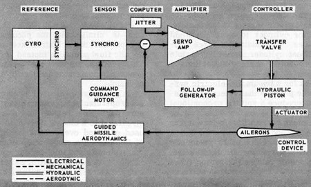 Figure 5A11.-Hydraulic-electric system for roll control. |
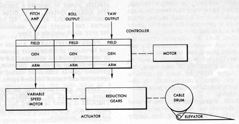 Figure 5A12.-Electrical system for pitch control. |
The speed of the controller drive motor must remain reasonably constant, regardless of loading. Otherwise, if the pitch output decreases, the speed of the motor would decrease; this would result in decreased output from the roll and yaw generators at the same time. As a result, there would be undesirable cross-coupling between control channels so that the pitch signal would affect other channels, and vice versa.
5A8. Energy sources
The energy required to operate the control surfaces may be taken from any of the following sources.
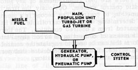
Figure 5A13.-How energy is obtained from the missile engine.
This system does not take power from the main engine and would be suitable for use when the main propulsion unit was cut off. The auxiliary engine will furnish power so long as fuel is available. If necessary, the auxiliary engine could be used to drive a generator and pump simultaneously to obtain power for hydraulic-electric or penumatic-electric systems.
COMPRESSED GASES. Air and other gases can be stored in tanks under pressure for use in operating control systems. As explained in the section on pneumatic controls, the compressed gas is exhausted during the control operation and cannot be used again.
Missile control is similar to any automatic control function. The system corrects some controllable quantity, and then checks the results as a basis for further corrections.
Factors that must be controlled by the missile control system are pitch, roll, and yaw. The system must provide a means of determining when the missile has departed from the desired attitude. Deviations are sensed by gyros. Electrical, mechanical, and electronic components are interconnected to form a complete control system.
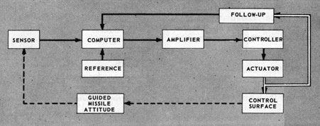 Figure 5B1.-Block diagram of missile control system. |
| 77 | ||
| surfaces, a means for measuring the magnitude and direction of errors, and a means for translating the error signals into control surface movement. | ||
5B3. Error-sensing devices
Deviations in missile pitch, roll, and yaw are detected by gyros. A minimum of two gyros is necessary for missile flight stabilization. Each gyro sets up a fixed reference line from which deviations are measured. One such reference is the spin axis of a vertical gyroscope; from this axis deviations about the pitch and roll axes can be measured, as shown in figure 5B2.
A second reference line is the spin axis of a horizontal gyro, set up parallel to the horizontal axis of the missile as shown in figure 5B3.
Gyros used for missile control applications are divided into two classes: gyros used for
Figure 5B3.-Horizontal reference line.
stabilizing (control) purposes and gyros used for both guidance and stabilization. If turns or other maneuvers are necessary, a third gyro is required so that there will be one gyro for each sensing axis.
In addition to the control signals from the vertical and horizontal gyros, which are proportional to the deviation of the missile from the desired trajectory, a signal that is proportional to the rate of deviation is required for accurate control and smooth operation. A RATE GYRO furnishes the rate of deviation signal.
A gyro that is being used for rate deviation indications has a restricted gimbal that is free to rotate about one axis only. The spin axis of a yaw rate gyro is mounted parallel to the missile line of flight. The roll rate gyro spin axis is parallel to the missile pitch axis, and at right angles to the line of flight. The pitch rate gyro spin axis is parallel to the yaw axis of the missile and at right angles to the line of flight.
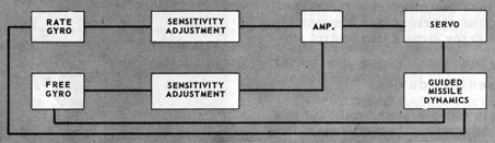 Figure 5B4.-A control channel using rate and free gyros. |
5B4. References
In order to accurately determine errors, the complete control system must have reference values built in. The system is then capable of sensing a change, comparing the change to a reference, determining the difference, then starting a process that will reduce the difference, to zero.
The reference units in a missile control system are of three kinds-voltage references, time references, and physical references. A more detailed discussion of references will appear in the next section of this chapter.
5B5. Correction-computing devices
5B6. Power output devices
The amplification of error signals is performed by a conventional vacuum-tube amplifier or a magnetic amplifier. Regardless of the method used, the prime purpose of an amplifier is to build up a small sensor signal to a value great enough to operate the controls.
5B7. Feedback loops
5C2. Types of reference
In the following discussion, the three types of reference signals will be described separately to show how each type functions in the complete control system.
VOLTAGE. In some control systems, the ERROR SIGNALS are in the form of an a-c voltage which contains the two characteristics necessary to make proper corrections in the flight path. These are the amount of deviation, and the direction of sense of the deviation.
The amount of deviation maybe indicated by the amplitude of the error signal so that, as the deviation increases, the amplitude increases; and if the deviation decreases, the amplitude decreases. Therefore, when the missile attitude has been corrected and there is no longer a deviation, the error signal amplitude drops to zero.
The direction of deviation may be carried by the a-c signal as a phase difference with respect to the phase of a reference signal. Only two phases are required to show direction of deviation about any one control axis. When a phase-sensitive circuit, such as a discriminator, is used to compare the error signal with the a-c reference signal, the direction of error is established and the output containing this information is fed to other control sections.
TIME. The use of time as a reference is familiar to everyone. One common application is in the automatic home washer. A clock-type motor drives a shaft, which turns discs that operate electric contacts. These contacts close control circuits that operate hot- and cold-water valves, start and stop the water pump, change the washer speed, spin the clothes dry, and finally shut off the power. Each operation runs for a specified time interval. This kind of timer can be used for certain missile control operations.
Timer control units vary considerably in physical characteristics and operation. All of them require an initial, or triggering, pulse. Since all timers in a complete system are not triggered at the same time, each must have its own trigger. This is usually an electrical signal. It may be fed to a solenoid which mechanically triggers the timing device.
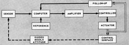 Figure 5C1.-Basic missile control system. |
| 80 | ||
| electrical signal to a motor. The motor, which is apart of a timing device, then starts the control sequence in much the same manner in a home washer. | ||
Mechanical timers are used in some missile control systems. In operation, these timers are similar to mechanical alarm clocks. The energy is stored in a main spring. If a mechanical timer is used in a missile, the clock mechanism is not started until the missile is in flight, and therefore some form of triggering linkage is necessary. This usually consists of a catch that can be released by a solenoid. Since the spring cannot be rewound after the missile has been launched, a mechanical timer can be used only once during a flight.
An arm connected to the output shaft serves as part of a switch contact system. The length of time required for the arm to travel from the starting position to the point where contact is made is the delay time of the unit. Normally, this mechanism is used only once during a missile flight. If recycling is necessary, a more complex unit is required.
 Figure 5C2.-Simple motor timer. |
 Figure 5C3.-Thermal delay tube. |
| 81 | ||
| without additional circuitry or mechanisms. However, they do not have the accuracy of clock timers. | ||
One type of thermal delay tube is shown in figure 5C3. Its components are the two bimetal strips, the contacts, a heating coil, and the strip supports. When a triggering voltage is applied, the heating coil heats ONE of the bimetallic strips. As the temperature rises, the strip deforms and its contact moves toward the other contact. When the bimetal strip has heated sufficiently, the contacts touch and the output circuit is completed.
The amount of time between application of the triggering voltage and closing of the contacts is determined by the contact spacing, the temperature characteristics of the metals in the strips, and the characteristics of the heater coil. The delay time is preset by the manufacturer; the assembly is then placed in a tube-type enclosure, and the air is pumped out of the tube. This type of construction prevents any adjustment of the time delay.
PNEUMATIC. Pneumatic timers may be used in certain missile applications. Time delay action is obtained by compressing air in a cylinder and then allowing the air to escape through a small orifice.
There are two general types of pneumatic timers-piston and diaphragm. The piston type is shown in figure 5C4. The felt washer acts as an air seal. As the plunger is pulled up, the spring is compressed and the contacts are opened. The spring is held in compression by the inertia block.
 Figure 5C4.-Piston-type pneumatic timer. |
 Figure 5C5.-Diaphram-type pneumatic timer. |
The diaphram-type pneumatic timer, shown in figure 5C5, operates on essentially the same principle as the piston-type timer that has been described.
Most missile control systems use some form of timer. Remember that an individual timer may be used to start a variety of control functions. Sometimes a timer is used strictly as a safety device.
PHYSICAL REFERENCES. There are a number of references for missile control systems other than the voltage and time classifications we have discussed. The remaining types have been grouped under the heading of physical references. They include gyros, pendulums, magnetic devices, and the missile airframes.
Some gyros are precessed to a vertical position by a pendulum device called a "pendulous pick-off and erection system." The complete gyro system is called a vertical gyro; it maybe used to measure the pitch and roll of a missile.
The sensor unit in a guided missile control system is a device used to detect deviation from the desired attitude. In this section, we will discuss the use of gyroscopes, altimeters, and transducers as sensing units. Gyroscopes are generally considered to be the basic sensor unit in any missile control system. Other types of sensors, such as altimeters and transducers, are classed as secondary units.
A gyroscope contains an accurately balanced rotor that spins on a central axis. Figure 5D1 shows a FREE GYRO that is mounted so it can tilt, or turn, in any direction about its center of gravity.
GYROSCOPIC INERTIA. The characteristic of a gyroscope that resists any force which tends to displace the rotor from its plane of rotation is called "gyroscopic inertia." Three factors determine the amount of inertia. These are: the weight of the rotor, the distribution of this weight, and the speed at which the rotor spins.
A gyro with a heavy rotor has more rigidity than one with a light rotor, if the speed of rotation is the same for both. Distributing the weight of the gyro to the outer rim of the rotor will give increased rigidity even though there is no increase in the weight of the rotor. An increase in gyro rigidity can also be obtained by increasing the speed of rotation.
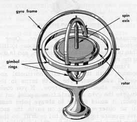
Figure 5D1.-Free gyroscope.
precession is sometimes called INDUCED PRECESSION.
The direction in which a gyro will precess, when an external force is applied, is shown in figure 5D2. A force applied to a gyro at its center of gravity does not tend to tilt the spin axis from its established position, and therefore does not cause precession. A spinning gyro can be moved in any direction without precession, if its axis can remain parallel to its original position in space. Therefore, the gyro can measure only those movements of the missile that tend to tilt or turn the gyro axis. Two gyros are needed for vertical and horizontal stabilization of missile flight. The spin axes of these gyros would be at right angles to each other.
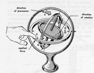
Figure 5D2.-Gyro precession.
because inertia fixes it in space. Over a period of time a gyro axis will appear to tilt. This is called apparent precession, and is due to the rotation of the earth.
Figure 5D3 represents a gyro at the equator, with the spin axis horizontal and pointed east-west. The earth turns in the direction shown by the arrow. If you could observe the gyro spin axis from a point out in space, it would appear to always point east. To an observer standing on earth, the spin axis appears to gradually tilt or drift, so that after three hours, the spin axis has tilted 45
This action gives the impression that the gyro has turned end for end, and that a complete revolution is made every 24 hours. But this is not true. Actually, the gyro axis has maintained its fixed direction in space; only the earth has moved.
The apparent precession of a gyro makes it unfit for use as a reference over an extended time unless some kind of compensation is used to keep the gyro in a fixed relation to the earth's surface.
GYRO DRIFT. Gyro error caused by random inaccuracies in the system is called drift. It has three principal causes-unbalance, bearing friction, and gimbal inertia.
Dynamic unbalance may occur because of operation at some speed or temperature other than for which the gyro was designed. Some unbalance exists in any gyro because of manufacturing tolerances.
An even amount of bearing friction all around a shaft does not cause drift. It will, however, cause the speed of rotation to change.
Energy is lost whenever a gimbal rotates, because of inertia. The larger the mass of the gimbal, the greater the drift from this source.
MOUNTING SYSTEMS. The main cause of random drift in gyros is friction in gimbal bearings. Figure 5D5 shows one type of mounting that has been developed to reduce this friction. It is called FLOATED GYRO UNIT.
The floated gyro unit is a viscous-damped, single-degree-of-freedom gyro with a microsyn torque generator and a microsyn signal generator mounted on its output shaft. The microsyn torque generator places a torque on the gyro gimbal.
In figure 5D5 the gyro wheel is contained within the damper housing. The microsyn signal generator units are mounted on the gyro shaft as shown in the drawing. The space between the damper housing and the gyro case is filled with a viscous damping fluid. Because of the high specific gravity of the fluid, it serves to float the gyro damper housing and gyro gimbal shaft, and thus reduces the gimbal bearing friction and drift. Thermostatically controlled heaters around the damping fluid space keep the fluid viscosity constant. If the gyro shown in figure 5D5 were mounted with its input axis parallel to the pitch of yaw axis of the missile, the torque applied to the output shaft would be proportional to the difference between the desired angular velocity of the missile and its angular velocity about the axis.
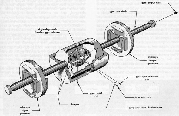 Figure 5D5.-Floated gyro unit. |
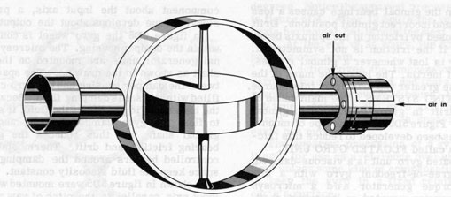 Figure 5D6.-Air bearing gyro. |
ERECTING SYSTEMS. Figure 5D7 is a block diagram that shows how signals from a precession sensor are used to maintain gyro stability. If the gyro spin axis in this system is vertical, the gyro output signal will be zero. If the spin axis moves away from the vertical, the gyro will send a voltage to the precession sensor. The amplitude of this voltage will depend on the amount of precession, and its phase of the direction of precession. The precession sensor output is amplified to operate the torque motor, which returns the gyro to the vertical position.
The gyro's spin axis, kept tangent to the earth's surface and slaved to the earth's magnetic field, provides a basic reference for missile heading. When the missile turns in either direction, the flux valve turns with it. When the flux valve turns, the angle between its coils and the earth's magnetic field is changed, and an error signal is generated. The error signal is amplified and used to operate controls that correct the missile heading.
RATE GYROS. The control signals furnished by the vertical and horizontal (free) gyros are proportional to the deviation of the missile. Another signal, proportional to the RATE of deviation, is required for smooth control. This is the RATE-OF-DEVIATION signal; it is supplied by a RATE gyro. A rate gyro has a restricted gimbal that is free to rotate about only one axis. Its construction is shown in figure 5D8.
 Figure 5D7.-Vertical gyro erection system. |
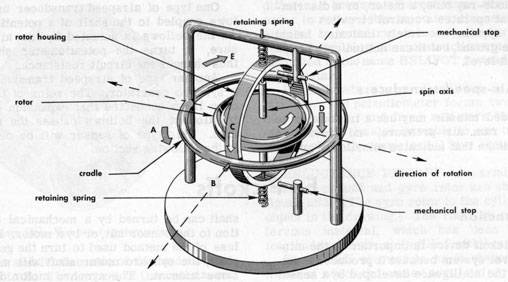 Figure 5D8.-Basic rate gyro. |
Displacement signals alone would give the missile a tendency to over-correct its errors, and yaw or pitch about its desired course. The displacement and rate of change signals minimize over-correction, and ensure stability.
PICKOFF SYSTEMS. A "pickoff" is a device that produces a useful signal from the intelligence developed by a sensor. The sensing devices for missile control generally indicate angular or linear displacement, measured with respect to some fixed quantity. The pickoff must be able to measure the amplitude and direction of the sensor displacement, and produce a signal that represents both quantities. Electrical pickoffs use phase relation or polarity difference to indicate direction. The ideal pickoff should have a linear output and minimum friction loss.
5D3. Altimeters
An altimeter measures altitude. There are two main types: PRESSURE and ABSOLUTE.
A pressure altimeter is a form of aneroid barometer. Its mechanism includes a bellow s-like chamber from which most of the air has been removed. The pressure of the atmosphere tends to collapse the bellows. The surface of the bellows is connected to a scale pointer through a mechanical linkage, which magnifies the bellows surface movement.
As the pressure does not remain constant at any one level, this type of altimeter may have an error due to variable atmospheric conditions.
The ABSOLUTE altimeter is sometimes called a radio altimeter. It indicates altitude above the ground, rather than above sea level. It is actually a form of radar, since it measures the time required for a radio pulse to reach the ground, be reflected, and return.
This system accurately indicates height above the ground, but it can not indicate height above sea level.
5D4. Air-speed transducers
The pickoff device is important to the missile control system because it produces a signal from the intelligence developed by a sensor unit.
5E2. Requirements
The signal produced by the pickoff must be suitable for use in the control system it is serving. The pickoff must have an output sense. That is, it must be able to determine the direction of displacement and then produce a signal that indicates the direction. In electrical systems the indication may be a phase or polarity difference.
The ideal pickoff should have a considerable change in output for a small movement of the pickoff. It should also have minimum torque or friction loss since these losses would be reflected to the sensor element and affect its operation. Small physical dimensions and light weight are additional requirements for pickoffs used in missiles. The null point (no output) should be sharply defined.
Electrical pickoffs in common use fall into four categories. Each has some characteristic that makes it suitable for certain applications.
To get better action as the null point is approached, a differential synchro system is sometimes used. In this system, two inputs-one electrical and the other mechanical-are fed to a synchro differential generator unit, which then furnishes a voltage equal to the sum or difference between the two inputs.
Synchro pickoffs are sometimes called selsyns, autosyns, or microsyns.
POTENTIOMETERS. A potentiometer is a variable resistance that is normally used as a voltage divider. The resistance element is formed into a circular shape and a moving arm makes contact with the element. By connecting leads to the ends of the strip from a voltage supply and then connecting a load to the moving arm and one end of the strip, the source voltage may be divided by varying the position of the arm on the strip.
The resistance used for many electronic applications is composed of a thin film of carbon deposited on an insulating material. This type of resistance element is not suitable for servo applications because the resistance changes with temperature, humidity and wear. These disadvantages are overcome by using a wire-wound resistance strip, as shown in figure 5E1.
Figure 5E1.-Wire-wound potentiometer.
to points A and B. One side of the load is also connected to B. The section of the resistance strip between the moving arm and A acts as a resistance in series with the load, and there is less voltage at the load that is being furnished by the source. If the moving arm is all the way down to B, the load will get no voltage.
Thus, the position of the moving arm determines the amount of voltage. It is also possible to use the variation in resistance as a control medium. Since the resistance between A and the moving arm and between B and the moving arm vary as the arm is moved, a null can be indicated when the two resistances are equal.
If the shaft of the potentiometer is mechanically coupled to the sensor, the output voltage will vary according to the moving arm displacement. However, the voltage does not change smoothly with this type construction. The jumpy output is due to the voltage
Potentiometers are often used in bridge circuits. The potentiometer forms two arms of the bridge, and fixed resistors form the other two. It is also possible to use two potentiometers to comprise all four arms of the bridge.
RELUCTANCE PICKOFF. A variable reluctance pickoff and gyro rotor are shown in figure 5E3. (The gyro rotor is the cylindrical object in the drawing.) The rotor is made of ferrous material, which has been slotted lengthwise and the slots filled with brass.
The pickoff element is an E-shaped metal mass, of which the center arm is a permanent Alnico (special alloy of aluminum, nickle, and cobalt) magnet. The outer arms, and the long side of the E, are made of soft iron. Coils are wound on each leg and connected in series opposition. As the gyro rotates, it causes regular variations in the magnetic flux paths as the brass and ferrous strips pass the end pieces. This establishes regular variations in flux density and induces an a-c voltage in the coils. However, because of the opposing connection of the coils, the induced voltages cancel.
The gyro spin and precession axes are shown by dashed lines. As the rotor precesses, the air gaps at each end vary oppositely (one increases and the other decreases) in proportion to the precessing force, and cause different induced voltages in the pickoff coils. Since the two voltages are different they no longer cancel, and the output voltage is that produced by acceleration. The output voltage is rectified by the crystal diode and filtered by the condenser. The resulting d-c voltage can be used as an acceleration signal. The polarity of the signal voltage depends upon which coil has the greatest induced voltage, and therefore indicates the direction of the acceleration.
Figure 5E4 shows another type of reluctance pickoff. The stator has four coils divided into two pairs. One pair is supplied with a constant-amplitude a-c voltage from a reference oscillator.
Voltage from one pair of coils is induced in the second pair through an armature. The
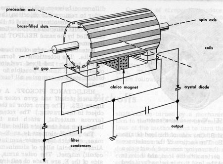 Figure 5E3.-Gyro rotor and reluctance pickoff. |
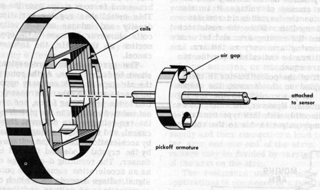 Figure 5E4.-Externally operated reluctance pickoff. |
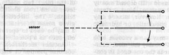 Figure 5E5.-Capacitance pickoff. |
Computers appear in missile systems in a variety of forms. The computer maybe a simple mixing circuit in a missile, or it may be a large console type unit suitable for use at ground installations only.
5F2. Function and requirements
One important function of a computer is the coding and decoding of information relating to the missile trajectory. It is necessary to code and decode control information in order to offset enemy countermeasures and to permit control of more than one missile at the same time.
Another function of the computer is the mixing of signals from sensor and reference units to produce error signals. Figure 5C1 shows, in block form, how the computer is linked with other sections of the complete system. The signals from the sensor and reference units may be mixed in a preset ratio, or they may be mixed according to programmed instructions.
The computer section may also compare two or more voltages to produce error signals. For this purpose, voltage or phase comparator circuits are added. The synchro units discussed in the previous section are used in computers to convert signal voltages into forms that are better suited for processing.
Airborne computers are generally classified according to the phase of missile flight in which they are used. The computers may be separate units or they may be combinations of prelaunch computer, launch computer, azimuth computer, elevation computer, program computer, and dive-angle computer.
5F3. Types of computers
In a missile control system, computer elements are of general types-mixers, integrators, and rate components.
Electronic mixers may use a vacuum tube as a mixing device. Probably the most common type of tube mixer is the one used in conventional superheterodyne radio sets. Here a tube mixes an incoming RF signal with the signal of a local oscillator to produce a difference frequency. It is also possible to use a network composed of inductors, capacitors, and resistors for mixing. Regardless of the type of mixer, the signals to be combined are represented by the amplitude and phase of the input voltages. Voltages from such sources as pickoffs, rate components, integrators, followup generators, and guidance sources may be combined by the mixer section to form control signals.
Another mechanical mixer uses gears to combine position or angular velocity information. The gear arrangement is similar to that of an automobile rear axle differential. If the input shafts contain position information, they will move slowly and maintain approximately the same average position. The position of the output shaft constantly indicates the difference between the two shaft positions. If the information is represented by the speed of the shaft rotation, the angular velocity of the output shaft represents the difference between the two input shaft speeds.
It is possible to arrange the input shafts so that the output represents the sum of the inputs rather than the difference. Weighting factors can be controlled by changing the gear ratios in the differential.
Sometimes information is transferred through air or hydraulic tubes. The signals are created by varying the pressure inside the tube. Two signals can be combined by joining two tubes into one.
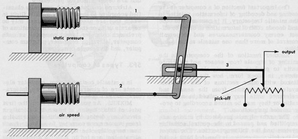 Figure 5F1.-Mechanical mixer. |
| 93 | ||
| integral of a constant signal is proportional to the amplitude multiplied by the time the signal is present. Assume that the integrator output is four volts when the duration of the constant input signal is one minute. Then if the same input signal had lasted for one-half minute, the output would have been two volts. | ||
But, an actual missile error signal is not constant, as we assumed in the above example. The amplitude and sense of the error change continuously. Even so, the integrator output is proportional to the product of the operating time and the average error during that time. Should the sense of the error change during the integration period, a signal of opposite sense would cause the final output of the integrator to decrease. The integrator can be considered as a continuous computer, since it is always producing a voltage that is proportional to the product of the average input voltage and time. Therefore, the integration of an error with respect to time represents an accumulation of intervals of time and errors over a specified period.
Any integrator has a lag effect. To see why this is true, let us visualize a situation like that shown graphically in figure 5F2. The solid lines forming the rectangles represent on-off signals plotted with respect to time. The polarity is represented by the position of the rectangle above or below the time reference line. The heavy white lines represent the integrated output signal.
Although the input signal goes from zero to maximum with zero time lag, there is no output at that instant. The graph shows the lag effect; note that time is required before the output reaches an appreciable amplitude. Approximately the same length of time is required for the output amplitude to drop to zero after the input pulse ends.
The figure also shows the additive effect of two successive negative pulses. This action is made possible by the time lag, and is used to give more precise control action.
The output signal from the integrator is used to support the proportional error signal, to make sure that enough correction will always be made by the control system.
Integration may be performed by a motor, the speed of which is proportional to the amplitude of the input signal. The motor drives a pickoff, and the distance the pickoff moves is proportional to the integral of the input signal.
The direction of motor rotation will depend on the polarity or phase of the input signal. The amplitude of the error signal varies irregularly; the sense of the signal may reverse, causing reversal of the motor rotation.
Other types of integrators use ball-and-disk mechanical arrangement, resistance-capacity (R-C) circuits, resistance-inductance (R-L) circuits, and thermal devices.
RATE SYSTEMS. The rate section in a missile control system should produce an output signal proportional to the RATE OF CHANGE of the input signal amplitude.
The preceding section showed that a time lag is present in integrator circuits. It is this time lag that makes rate circuits necessary. Missile deviation cannot be corrected instantly, because the control system must first detect an error before it can begin to operate.
The ideal control system would have zero time lag, thus permitting zero deviation during the missile flight. All design efforts are toward a control system with this degree of perfection. Control surfaces are designed to correct missile flight deviations rapidly. The control surfaces are moved rapidly by actuators, which are operated by amplified error signals. But it is possible to have a signal so large that the missile is driven beyond the desired attitude, and an error occurs in the opposite direction. This error drives the missile back in the first direction. The end result is a series of swings back and forth across the desired trajectory.
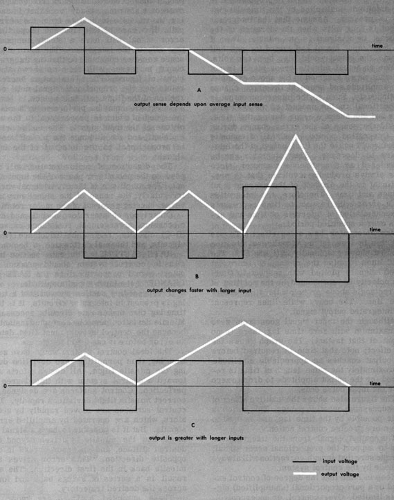 Figure 5F2.-Integrator time lag and sense. |
| 95 | ||
| the oscillation. The amount of damping may be classed as CRITICAL, UNDERDAMPING, or OVERDAMPING. | ||
The end effect of a rate signal is a reduction in the time between the initial control pulse and the output action. To reduce this time, the rate signal is combined with the proportional signal to produce a resultant signal that leads the original proportional signal.
Amplifiers are divided into two groups-POWER and VOLTAGE. Both are used in missile control systems to build up a weak signal from a sensor so that it can be used to operate other sections of the control system. These sections normally require considerably more power or voltage than is available from the sensor. Most amplifiers use electronic tubes, but in this section we will discuss some of the less conventional amplifiers.
5G2. Operating principles
Some functions in missile control systems require a series of flat-topped pulses, called square waves, at a definite frequency. It is possible to convert other wave shapes to square waves with vacuum tube amplifiers and clippers. It is also possible to accomplish the same result with a mechanical device known as a chopper.
The contact arrangement is shown near the bottom of the drawing. Leads are brought out separately from each of the two fixed contacts and the vibrating reed to pins on the base. These pins are arranged so that the chopper can be plugged into a conventional radio tube socket. In order to reduce operating noise, the entire mechanism is enclosed in a sponge rubber cushion before it is placed in the metal can. By using the chopper in connection with a conventional transformer, amplification can be obtained at the pulse frequency.
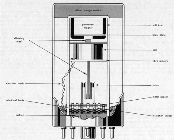 Figure 5G1.-Cutaway view of mechanical chopper. |
| H. Controller Units | ||
| 5H1. Function | ||
A controller unit in a missile control system responds to an error signal from a sensor. In certain systems an amplifier which is furnishing power to a motor serves as a controller. In this section we will discuss controller units other than amplifiers.
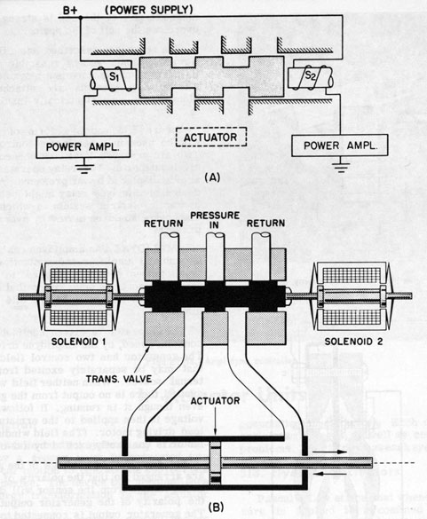 Figure 5H1.-a. Transfer valve (closed). b. Hydraulic transfer valve and actuator. |
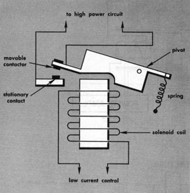
Figure 5H2.-Low current relay.
The relay just described has a fixed core. However, some relays resemble a solenoid in that part of the core is a movable plunger. The moving contacts are attached to the plunger, but are electrically insulated from it.
Figure 5H3 shows a form of relay that can be used in a penumatic control system. Two air pressure lines are connected to the air input ports. The relay operates when its arm is displaced by air pressure. A modified design of this type relay might be used in a hydraulic-electric system in which case the diaphragm would be moved by hydraulic fluid pressure.
AMPLIDYNE. An amplidyne can be used as a combined amplifier and controller, since a small amount of power applied to its input terminals controls many times that amount of power at the output. Figure 5H4 shows an amplidyne.
The generator is driven continuously, at a constant speed, by the amplidyne drive motor. The generator has two control field windings that may be separately excited from an external source. When neither field winding is excited, there is no output from the generator, even though it is running. It follows that no voltage is then applied to the armature of the load driving motor. (The field winding of the motor is constantly excited by a d-c voltage.)
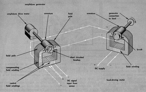 Figure 5H4.-Amplidyne controller. |
| I. Actuator Units | ||
| 5I1. Function | ||
In a missile control system, any error detected by a sensor must be converted into mechanical motion to operate the appropriate control device. The device that accomplishes this energy transformation is the actuator unit.
The actuator for a specific control system must be selected according to the characteristics of the system. The actuator must have a rapid response characteristic, with a minimum time lag between detection of the error and movement of the flight control surfaces. At the same time, the actuator must produce an output proportional to the error signal, and powerful enough to handle the load.
5I2. Principal types
5I3. Hydraulic actuators
Pascal's Law states that whenever a pressure is applied to a confined liquid, that pressure is transferred undiminished in all directions throughout the liquid, regardless of the shape of the confining system.
This principle has been used for years in such familiar applications as hydraulic door stops, hydraulic lifts at automobile service stations, hydraulic brakes, and automatic transmissions.
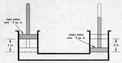 Figure 5I1.-Hydraulic system with equal piston displacement. |
Figure 511 shows that equal input piston displacement will produce the same output piston movement. Actually, this statement is not wholly true because of slight friction and compressibility losses. But for all practical purposes, the motion can be considered to be the same for equal piston displacements.
In the practical application of hydraulics, something must be done to keep fluid in the proper lines. To accomplish this a circulating system is used. This requires pressure, which is furnished by a pump.
PUMPS. The pump used in a hydraulic system must be driven by some power source, usually an electric motor, within the missile. Pumps used in missile systems generally fall into two categories-gear and piston.
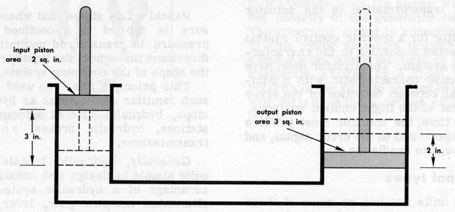 Figure 5I2.-Proportional hydraulic piston displacement. |
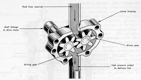 Figure 5I3.-Gear type pump. |
As the gears turn past the intake port, fluid is trapped between the gear teeth and the housing. This trapped fluid is carried around the housing to the output port. Because the fluid then has no place else to go, it is forced into the high-pressure delivery line.
When the piston reaches the left side of the cylinder, it reverses direction. This creates pressure against valves Nos. 1 and 4 so that valve 1 closes and valve 4 opens. At the same time, valve 3 closes and valve 2 opens.
RESERVOIR. The reservoir shown in figure 514 is a storage compartment for hydraulic fluid. Fluid is removed from the reservoir by the pump, and forced through the hydraulic system under pump pressure. After the fluid has done its work, it is returned to the reservoir to be used again. The reservoir is actually an open tank because of the atmospheric pressure inlets.
VALVES. The valves in the illustrated piston pump are of the flap type, which operate with very small changes in pressure. Another type of valve used in hydraulic systems is the pressure relief valve. As its name implies, it is used to prevent damage to the system by high pressures. Some combination systems use hydraulic pressure regulating switches instead of pressure relief valves.
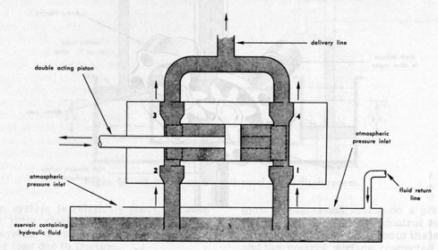 Figure 5I4.-Double-action piston pump. |
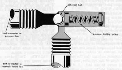 Figure 5I5.-Pressure relief valve. |
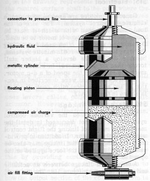
Figure 5I6.-Floating-piston hydraulic accumulator.
a storage space called a hydraulic accumulator is used. The accumulator also serves to smooth out the pressure surges from a double-action pump, which would otherwise cause unsteady operation of control devices to which the actuators are connected.
In operation, the air chamber is charged, through the bottom fitting, with compressed air until the chamber pressure equals the line pressure desired in the hydraulic system. This pressure forces the piston up toward the top of the cylinder. The cylinder is connected to the hydraulic pressure line through the fitting at the top. If the line pressure becomes greater than the air pressure, fluid is forced into the accumulator, and forces the piston down against the air pressure. Should line pressure drop, the air pressure forces the piston up and puts fluid back in the line. This action smooths out variations in pressure during periods of heavy loading, or when the pressure pump lags.
Another type of hydraulic accumulator, the diaphragm type, is shown in figure 5I7. It is built in the form of two hemispherical chambers, which are separated by a flexible diaphragm. Air pressure forces the diaphragm upward. If the system pressure becomes greater than the air pressure, fluid is forced into the fluid chamber. When the system pressure drops, air pressure in the accumulator forces the working fluid back into the system. The diaphragm-type accumulator serves the same purpose in a hydraulic control system as the piston type.
ACTUATOR. The purpose of a hydraulic actuator in a missile control system is to convert fluid pressure into mechanical force great enough to move a control device.
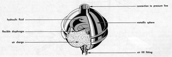 Figure 5I7.-Diaphragm-type accumulator. |
| 104 | ||
| load. It is possible to have a double-acting piston-type actuator in which hydraulic fluid under pressure can be applied to either side of the piston. A double-action actuator is shown in figure 5H1b. | ||
5I4. Pneumatic
The principal difference between a hydraulic system and a pneumatic system is the use of air rather than hydraulic fluid, as the working medium.
In a pneumatic system, air from a pressure tank passes through delivery tubes, valves, and pressure regulators to operate mechanical units. After the air has done its work, it is exhausted to the atmosphere. It cannot be returned to the tank for reuse. Consequently, air must be stored at a much higher pressure than is necessary for operating the loads in order to have enough pressure to operate the controls as the air supply in the tank diminishes.
Generally, motors are used as actuators in electrical control system. The size of the load, and the speed with which it must be moved, determine the type of motor to be used. D-c motors are most often used for driving the heavy loads encountered in missile systems, because d-c motors develop a higher stall torque than do a-c motors. In addition, it is much easier to vary the speed of a d-c motor.
Electrical systems were described in section A, and an electrical pitch control system is shown in figure 5A12.
5I6. Mechanical linkage
We have discussed the various control systems, but have not discussed in detail the mechanical means of linking the flight control surfaces to the actuator. In addition to providing a coupling means, the linkage may also be used to amplify either the force applied or the speed of movement.
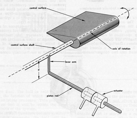 Figure 5I8.-Actuator and load linked by lever arm. |
| 105 | ||
| d, on the drawing represents the distance from the control surface shaft to the point where the force is applied. The control surface moves because force exerted by the piston is applied at a distance from the axis of rotation, and thus produces a torque. Other mechanical linkages may consist of an arrangement of gears, levers, or cables. | ||
5I7. Combination systems
Often a number of mechanical systems will be grouped together to form a combination system, as shown in figure 519. This system uses levers, cables, pulleys, and a hydraulic actuator. However, a system using this kind of control is not suited for high speed missiles.
5I8. Followup units
In operation, the followup signal combines with the error signal so as to oppose it. But, the error signal is the larger of the two, and is strong enough to produce the necessary control surface deflection. The error signal amplitude decreases as the missile approaches the correct flight path. When the amplitudes of the error and followup signals are equal, there is no further deflection of the flight control surfaces, because the sum of the two signals is zero.
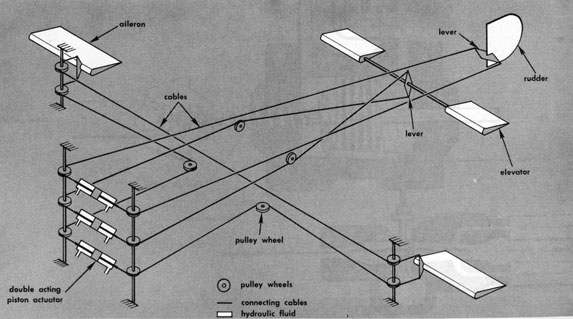 Figure 5I9.-Combination mechanical linkage. |
| 515354 O-59-8 |
| 106 |
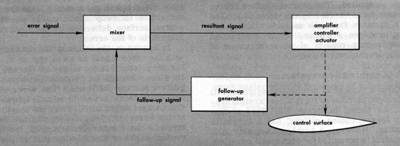 Figure 5I10.-Followup loop of missile control system. |
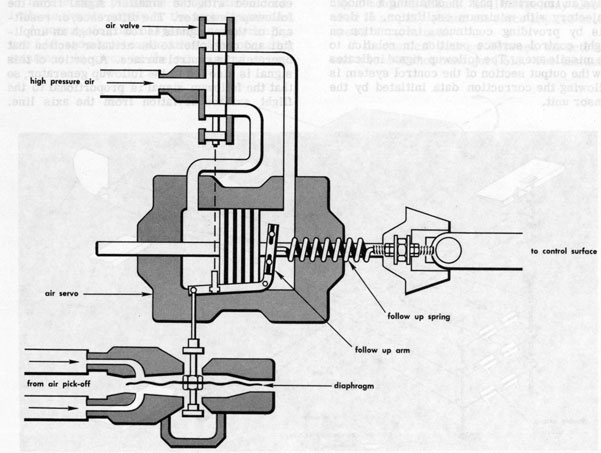 Figure 5I11.-Air relay with mechanical followup. |
| 107 | ||
| It is also possible to use a mechanical followup. When this method is used, the follow-up mechanism maybe a part of an air relay as shown in figure 5I11. The control surface position in relation to the missile axis is indicated by a force which is reflected to the controller by a spring. | ||
From an offensive viewpoint, a missile can be considered as a long-range artillery projectile. In its basic form, a missile is a self-propelled, high-explosive weapon. Like a projectile, it must be carefully aimed in order to follow a trajectory that will take it to the target.
Missiles like projectiles, are influenced by natural forces such as cross winds. But, because a missile usually makes a much longer flight than a projectile, it is subjected to these natural influences for a longer time.
A missile is a very expensive piece of ordnance. If the conventional artillery practice of firing several ranging shots were followed, the cost would be prohibitive. And unguided missiles would be of little value against moving targets, which can take evasive action.
All of these factors add up to this: an accurate means of guiding a missile to its target is an absolute necessity.
Modern guidance systems are far advanced. But progress in electronic and allied equipments is rapid, and our present guidance systems may be out of date within a few years. The ultimate system may be a composite formed from the systems you will read about in this and the following chapters, or it may be entirely different from any of them.
6A2. Definitions
6A3. Purpose and function
The purpose of a guidance system is to control the path of the missile while it is in flight. This makes it possible for personnel at ground or mobile launching sites to hit a desired target, regardless of whether that target is fixed or moving, and regardless of whether or not it takes deliberate evasive action. The guidance function may be based on information provided by sources inside the missile, or on information sent from fixed or mobile control points, or both.
6A4. Basic principles
The guidance system in a missile can be compared to the human pilot of an airplane. One guidance system uses an optical device that guides the missile to the target in much the same way as a pilot, using landmarks for bearings, guides a plane to a landing field.
If landmarks are obscured, the pilot must use another system of guidance. He could, for example, use radio beams. One missile guidance system uses radio or radar beams for guidance; another uses radio to send information to the missile, just as a ground control station might send instructions to a pilot.
We have mentioned radio and radar as primary guidance controls, but these are not the only methods by which a missile trajectory can be controlled. Heat, light, television, the earth's magnetic field, and loran have all been found suitable for specific guidance purposes. Information on all these systems will be given in later chapters.
For purposes of explanation, missile guidance may be divided into three separate phases. The first is known as the LAUNCHING, or INITIAL phase. The second is called the MIDCOURSE phase, and the last is called the TERMINAL phase. These names refer to different parts of the missile flight path.
6B2. Initial phase
Missiles may be launched from a point at some distance from the guidance equipment. Because the missile does not have aerodynamic stability when it is first launched, the flight controls are locked in the neutral position, and remain locked for a short time after launching. As soon as the controls are unlocked, and the guidance system assumes control, the initial phase of guidance is completed.
6B3. Midcourse phase
6B4. Terminal phase
The terminal phase is of great importance because it can mean a hit or a miss. The last phase of surface-to-air missile guidance must have high accuracy as well as fast response to guidance signals.
A missile guidance system involves a means of determining the position of the missile in relation to known points. The system may obtain the required information from the missile itself; it may use information transmitted from the launching station or other control point; or it may obtain information from the target itself. The guidance system must be stable, accurate, and reliable.
Acoustic sensors called hydrophones are often used in torpedo guidance systems. Essentially, a hydrophone is a microphone that works underwater. It picks up the vibrations of ships' propellers, and the torpedo can "home" on this noise. Acoustic sensors are not well suited for airborne missiles.
Heat, or infrared sensors use an active element called a THERMOCOUPLE, or an element known as a BOLOMETER. Either sensor may be used with a lens and reflector system.
Sensors that respond to light use an active element called a PHOTOELECTRIC cell. Another light-sensing system uses a television camera to pick up information and send it back to the launching site by means of a TV transmitter in the missile.
Electromagnetic sensors use radio or radar antennas as active elements. The phase of guidance determines the location of the antenna in the missile structure. For initial and midcourse guidance the antenna is normally streamlined into the tail of the missile. For final phase guidance the sensor may be located in the nose of the missile.
All of these sensors have advantages and disadvantages. Some are well suited for final phase applications and totally unsuited for initial and midcourse guidance. The advantages and disadvantages of each will be covered in later chapters.
6C3. Reference units
The signals picked up by the sensor must be compared with known physical references such as voltage, time, space, gravity, the earth's magnetic field, barometric pressure, and the position of the missile frame. The sensor signal and the reference signal are compared by a computer, which will generate an error signal if a course correction is necessary. The error signal then operates the missile control system.
Gyroscopes are used for space reference. A reference plan is established in space, and the gyro senses any change from that reference.
An instrument called a FLUX VALVE, has the ability to sense the earth's magnetic field, and can be used for guidance. The primary purpose of this device is to keep a directional gyro on a given magnetic heading. A gyro operated in this manner may be used to govern the yaw controls of a missile.
Barometric pressure can be used to determine altitude. A guided missile that is set to travel at a predetermined altitude may use an altimeter to sense barometric pressure. Should the missile deviate from the desired altitude, an error signal will be generated and fed to the control section.
Another pressure-type sensor is used to determine airspeed. It compares static barometric air pressure with ram air pressure. The difference between these two pressures provides an air speed indication.
The axis of the missile frame is used as a reference to measure the displacement of the missile control surfaces. (The movement of the control surfaces cannot be referenced to the vertical, or to a given heading, because the reference would change when the missile position changes.)
Selsyns may be used to indicate the angular position of the flight control surfaces with respect to the missile axis. It is also possible to use potentiometers (variable resistors) for this purpose. When this method is used, the potentiometer is fastened to the missile frame and the potentiometer wiper-arm shaft is moved by the control surface.
6C4. Amplifiers
Each of the sensor units we have discussed produces an output; in most cases this output is a voltage. A computer is used to compare the sensor output voltage with the reference voltage. If the missile is off course, the two voltages will not be the same. The computer will then generate an error signal, which will be used to operate the missile control surfaces and bring the missile back on course.
In an amplifier, the small power available in the input signal is used to CONTROL the amount of power that is supplied from another source. Thus, in a sense, a relay or a switch is an amplifying device. A small amount of power applied to the relay primary, or to the switch handle, will close the contacts and thus apply a much larger amount of power to the load. But a switch or relay is an all-or-nothing device; the contacts are either open or closed. Many missile applications require an amplifier whose output is not only greater than the input, but also proportional to the input. For example, let's say that a sensor provides a one-volt input to an amplifier, and the amplifier output is 15 volts. Then, if the sensor supplies a three-volt input, the amplifier output must be 45 volts.
Electronic amplifier circuits can be designed to give proportional amplification for a limited range of input voltages. Electronic amplifiers have become familiar devices. An electronic amplifier is used to amplify the output of a record-player pickup to the power level required to drive a loudspeaker cone. Electronic amplifiers are used to amplify the signals picked up by a radio antenna. (But note that, in both cases, the actual power of the input signal is not increased. The input power is used simply to control the power supplied from another source-either batteries or the a-c line.)
Let's consider a very simple application, in which a vacuum tube is used as a switch. Let's say that we want a relay to operate when light falls on a photoelectric cell (fig. 6C1). If we apply a voltage across a photoelectric cell, and the cell is dark, the current flowing through it will be close to zero. But the current will increase slightly when light falls on the cell. Because the current in the photo tube circuit is only a few millionths of an ampere, it is not sufficient to operate a relay. But if we connect a resistance in series with the photo cell, this current will develop a voltage across the resistance, in accordance with Ohm's law. By using a very large resistance in series with the photo tube we can develop several volts across it, even though the power is very small. This voltage can be applied to the grid of a vacuum tube. Then, when light falls through the photo cell, current will flow through the vacuum tube; when the cell is dark, no current will flow. In this way, the flow of current CONTROLLED by the photo cell may be several thousand times as much as the current that actually flows through it. Finally, we can connect the coil of a suitable relay in series with the vacuum tube, between
A vacuum tube is more often used to amplify an a-c input signal (fig. 6C2). For this purpose, a plate load resistor is connected in series with the tube, between the plate and the positive terminal of the power supply. A changing current through the tube will then produce a corresponding change across the load resistor, in accordance with Ohm's law. In most circuits a steady, negative d-c voltage is applied to the grid. When no input signal is present, this negative "bias" voltage maintains the tube current at about half its maximum value. When an a-c input signal is applied to the grid, it will alternately add to and subtract from the fixed bias. The plate current, and consequently the plate voltage, will follow the input signal, but at a much increased amplitude. The output signal is taken

Figure 6C2.-Vacuum tube used as a-c amplifier.
from the plate, usually through a capacitor. This output can, of course, be used as the input for a second stage of amplification, so that extremely small signals can be built up to useful levels.
Another amplifying device is the MAGNETIC AMPLIFIER. In its simplest form, this device is basically a transformer with a saturable core, and a third winding in addition to the usual primary and secondary (fig. 6C3). With no current in the third winding, the device acts like a transformer, and an a-c voltage is developed in the secondary circuit. By passing d-c through the third winding, the core can be saturated; there is then no transformer action, and the secondary develops no voltage. A varying input signal on the third winding produces a corresponding variation, of greater amplitude, across the output. Most of the magnetic amplifiers now in use are more sophisticated than the one described here; they have additional windings, and serve a variety of purposes.
A magnetic amplifier is a reliable device because it is rugged, and resistant to shock, vibration, and temperature changes. It is used in a number of missile applications.
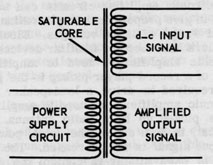
Figure 6C3.-Simplified diagram of magnetic amplifier.
6C5. Computer
An important function of a computer is the coding and decoding of information relating to the missile trajectory. In order to make the proper selections, the computer uses discriminator circuits to select pulses of the proper width, amplitude, frequency, phase, or time difference, and reject all other pulses. By using a number of different discriminators, a wide variety of pulse characteristics can be handled. The discriminator is relatively insensitive to manmade electrical noises and atmospheric static.
A second important computer function is to compare the signals from the sensor and reference units, to compute the missile's position with respect to the desired reference planes, and to generate error-signal voltages of the polarity and amplitude required to bring the missile back on course.
Computers may be divided, according to the way they operate, into two classes: ANALOG and DIGITAL. An analog computer deals with quantities that are continuously variable. A target bearing angle, for example, is such a quantity; in an analog computer, such a quantity can be represented with considerable accuracy by a voltage, or by the angle of rotation of a shaft. Digital computers, on the other hand, deal only with quantities that vary by distinct steps. For example, an angle might be represented as either 67° or 68°, but not as anything between those values. (A more complex computer might represent the same angle as either 67.43° or 67.44°, but would be incapable of dealing with any value between those two.) An ordinary slide rule is a simple analog computer, in which the position of the slide is "analogous" to the quantity represented. A desk calculating machine, or an abacus, is a simple digital computer.
In an electronic analog computer, the input and output variables are represented by voltages, and the computations are performed by electronic circuits. A type of electronic analog computer that has proved useful in missile design is the DIFFERENTIAL ANALYZER. This device is sometimes called a SIMULATOR, because it can be given electrical inputs that simulate both the characteristics of a proposed missile and the conditions under which it will operate. The action of the computer will then show how the proposed missile will perform under the specified conditions. It is thus possible to test new missile designs without building actual prototype missiles, and this procedure results in a considerable saving in both time and money.
6C6. Controllers and actuators
If a missile wanders off its proper course, this fact will be detected by the sensing mechanism previously described. The computer within the guidance system will evaluate the information provided by the sensing mechanisms, determine the direction and magnitude of the error in missile course or position, and produce a suitable error signal output.
At this point, the functions of the guidance and control systems overlap. The primary purpose of the control system is to correct errors in the attitude of the missile. The primary purpose of the guidance system is to correct errors in the missile flight path. Both types of error are corrected in the same way: by moving the missile flight-control surfaces. Movements of these surfaces are governed by the same controllers and actuators, regardless of whether the error signal is developed by the guidance or the control system.
The final section of a guidance system is known as a "feedback" or "follow-up" unit. This unit measures the position of the flight control surfaces in relation to the reference axis of the missile, and compares this value with the error signal generated by the computer.
Without the follow-up signal, there would be nothing but the varying air pressure to prevent the flight control surfaces from swinging to their maximum limits any time the sensor caused an error signal to be generated. By using feedback, the deflection of the flight control surface can be made proportional to the size of the error. The feedback loop thus gradually returns the flight control surfaces to neutral as the error is corrected.
To accomplish these results, the feedback signal is used to oppose the error signal. When the feedback signal becomes as large as the error signal, no further deflection of the flight control surface takes place because the two signals are equal and opposite, and their sum is zero.
As the missile approaches the desired course, the error signal becomes less than the feedback signal, and the resultant voltage difference reverses polarity. The reversal in polarity moves the flight control surfaces in the opposite direction until they are in neutral. This action is smooth and rapid, and cannot be duplicated by systems that use ON-OFF switching.
Figure 6C4 shows the relationship between the follow-up and error signals, and shows how the flight path is smoothed by combining these signals. Note how much smoother the lower path is than the upper path, which uses the error signal alone.
The discussion of feedback loops completes the basic discussion of the individual stages of a missile guidance system which is shown in block form in figure 6C 5.
The term PRESET completely describes one guidance method. When preset guidance is used, all of the control equipment is inside the missile. This means that before the missile is launched, all information relative to target location and the trajectory the missile must follow to strike the target must be calculated. After this is done, the missile guidance system must be set to follow the course to the target, to hold the missile at the desired altitude, to measure its air speed, and at the correct time, cause the missile to start the terminal phase of its flight and dive on the target.
The term COMMAND is used to describe a guidance method in which all guidance instructions, or commands, come from sources outside the missile. To receive the commands, the missile contains a receiver that is capable of receiving instructions from ground stations or from another aircraft. The missile receiver then converts these commands to guidance information, which is fed to the sections following the sensor unit.
We will list several command guidance systems and briefly describe them. Other chapters in this book will describe these systems in more detail.
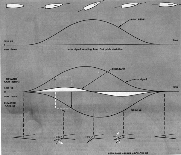 Figure 6C4.-Relationship of follow-up to error signal. |
LORAN PRINCIPLE. A loran system is a modern electronic aid to navigation. The name "loran" was derived from the words "LOng RAnge Navigation." The effective range of loran is as much as 1400 miles at night and about 750 miles during the day. The accuracy is comparable to that which can normally be expected from good celestial observations.
Loran lines are fixed with respect to the earth's surface, and their determination is not dependent on a compass, chronometer, or other mechanical device. The signals are on the air and available 24 hours per day, and cover the major part of the seas and oceans of the world.
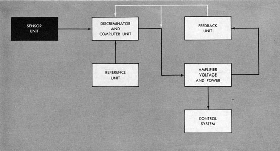 Figure 6C5.-Block diagram of missile guidance system. |
2. These signals are received aboard ship, plane or missile on a special loran indicator.
3. The difference in times of arrival of the signals from the two radio stations is measured on a special loran indicator.
4. This measured time-difference is used to directly determine, from charts, a line-of position on the earth's surface.
5. Two lines-of-position, determined from two pairs of transmitting stations, are crossed to obtain a loran fix.
Since radio signals travel at a constant speed, a direct relationship exists between the time of travel and the distance covered during that time. Therefore, a measure of time, is, in essence, a measure of distance. With these features it is easy to see how loran could be used as the basis for a missile guidance system.
The master starts the transmission cycle by sending out a pulse of radio energy which is radiated in all directions. After traveling the distance between the two transmitting stations, which is known as the "baseline," the pulse arrives at the slave. The signal is received at the slave by a loran receiver and the time of the signal arrival is used by the slave as a reference for the transmission of its own signal.
After the slave has sent its pulse, the whole process is repeated again and again.
If loran is to be used as a form of command guidance, the sensor in the missile must be suitable for loran use. A suitable receiving system is described in chapter 7.
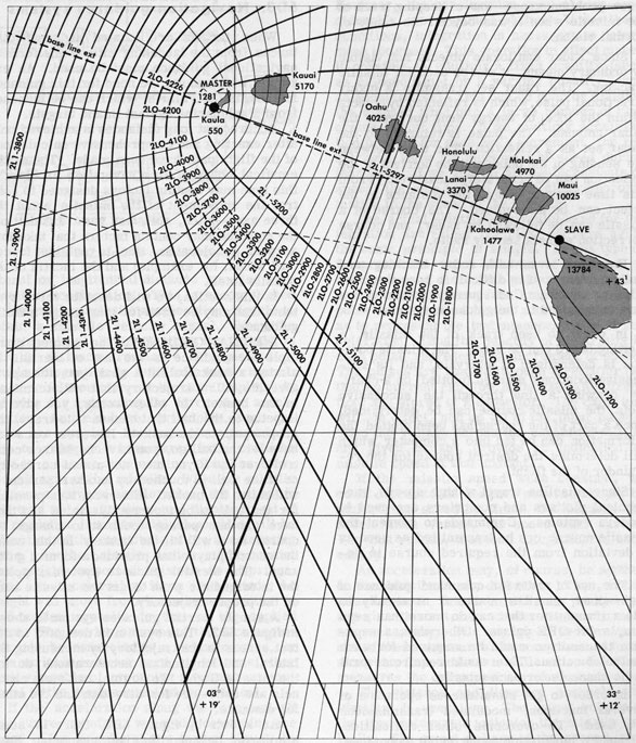 Figure 6D1.-Hyperbolic lines-of-position generated by two transmitters. |
| 118 | ||
| a new problem arose-that of keeping track of the missile when it was beyond the range of normal vision. | ||
Since radar can locate objects not visible by ordinary means, it can be used for missile tracking. The radar set transmits a highly directional pulse, which is reflected by objects within the lobe of energy sent out from the radar antenna. The pulse is returned to the radar set as a reflection. The time between the sending of the pulse and the arrival of the reflection can be accurately measured. From this time measurement, the distance to the object can be determined. The course of a missile can be followed by radar, and course correction signals sent by radio.
However, even with radar tracking and radio guidance, it is difficult to keep the missile on course. Consequently, other items have been added to the guidance system.
In order to keep track of the missile, a plotting board can be used. The missile position is determined at intervals, and its successive locations marked (plotted) on a chart. By drawing a line through the successive plots, the missile course can be determined. Once a part of the course has been plotted, the information can be fed into a computer which will determine the desired course for the remainder of the flight.
Since missiles travel at high speeds, mechanical plotters and computers are used in modern systems. Commands to correct the missile course can be transmitted as soon as a deviation from the required course is detected.
The use of radio for command guidance of high-speed missiles makes it necessary to use a transmitter that can do more than send simple ON-OFF pulses. Otherwise, a separate transmitter would be required for each control function. This would require several radio channels for each missile.
When targets are located at great distances from the launching site, some form of navigational guidance must be used. An example, which shows the need for this guidance method, is the Polaris, which can be launched from a submarine against inland targets.
Accuracy at long distances is achieved only after exacting and comprehensive calculations of the flight path have been made. The mathematical equation for a navigation problem of this type may contain factors designed to control the movement of the missile about the three axes-pitch, roll, and yaw. In addition, the equation may contain factors that take into account acceleration due to outside forces (tail winds, for example) and the inertia of the missile itself.
In this section, we will describe three systems that may be used for long-range missile guidance.
INERTIAL GUIDANCE. The simplest principle for guidance is the law of inertia. In aiming a basketball at a goal, you attempt to give the ball a trajectory that will terminate in the basket. In other words, you give an impetus to the ball that causes it to travel the proper path to the basket. However, once you have let the ball go, you have no further control over it. If you have not aimed correctly, or if the ball is touched by another person, it will miss the basket. However, it is possible for the ball to be incorrectly aimed and then have another person touch it to change its course so it will hit the basket. In this case, the second player has provided a form of guidance. The inertial guidance system supplies the intermediate push to get the missile back on the proper trajectory.
A simple inertial guidance system is shown in figure 6D2. This system is designed to detect errors in the trajectory by measuring the lateral and longitudinal accelerations during the missile flight. To do this, two main channels are used-one for direction and the other for distance.
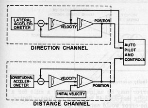
Figure 6D2.-Inertial guidance system.
lateral or longitudinal distance traveled as a result of acceleration. This is accomplished by integrating missile acceleration signals to obtain a missile velocity signal. When the velocity signal is integrated, the result is missile distance traveled. This method of double integration is built into each channel.
An accelerometer, as its name implies, is a device for measuring the force of an acceleration. In their basic principles, such devices are simple. For example a pendulum, free to swing on a transverse axis, could be used to measure acceleration along the fore-and-aft axis of the missile. When the missile is given a forward acceleration, the pendulum will tend to lag aft; the actual displacement of the pendulum from its original position will be a function of the magnitude of the accelerating force. Another simple device might consist of a weight supported between two springs. When an accelerating force is applied, the weight will move from its original position in a direction opposite to that of the applied force. The moving element of the accelerometer can be connected to a potentiometer, or to a variable inductor core, or to some other device capable of producing a voltage proportional to the displacement of the element.
If the acceleration along the fore-and-aft axis were constant, we could determine the speed of the missile at any instant simply by multiplying the acceleration by the elapsed time, in accordance with the formula
The actual electronic circuits used for integration are rather complex, but here again the basic principle is simple. In one type of integrator the input consists of a series of evenly spaced electrical pulses representing increments of time. The amplitude of each pulse is controlled by the accelerometer, so as to represent the instantaneous value of acceleration. Thus the quantity of electricity in each pulse represents an increment of speed. The pulses are passed through a rectifier (so that no current can flow in the opposite direction) and stored in a capacitor. The capacitor will, in effect, add up all of the input pulses. Thus the voltage across the capacitor will, at any given instant, provide an indication of missile speed at that instant.
If the missile speed were constant, we could calculate the distance covered simply by multiplying speed by time. But because the acceleration varies, the speed also varies. For that reason, a second integration is necessary.
An acceleration may, of course, be applied to the missile in any direction. Thus, if the missile is to determine its own position at any given instant, two accelerometer channels are necessary. For any given acceleration, one of these measures the component of force along the fore-and-aft missile axis; the other measures the component across that axis.
The distance and direction channels are identical in operation. The output voltage of the first integrator indicates the missile velocity. The output voltage of the second integrator is proportional to the distance the missile has traveled.
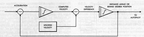 Figure 6D3.-Specified velocity reference. |
This method of determining when the missile reaches the target has the disadvantage of requiring large integrator and comparison voltages if long distances are involved. However, this disadvantage may be overcome by specifying short distance comparison points throughout the flight. The specification of comparison points can be done by a recorder carried in the missile.
Another method that may be used to hold down required voltages for long trips is to specify the velocity and use that as a reference condition on the first integrator output. This method is shown in block diagram form in figure 6D3.
When this system is used, any error above or below the specified velocity is fed to the second integrator. The resultant output is proportional to the missile error in distance at a given time.
Other information on inertial guidance systems will be given in a later chapter in this book.
CELESTIAL REFERENCE. Navigation by fixed stars and the sun has been practiced for years, and is very dependable.
One method that may be used to overcome the random drift error involves the use of star sights. The checking is done in much the same manner as a human navigator would check his position by observing an object, such as a star, having a known position.
To make the check, an automatic sextant is mounted on a platform in the missile so that it can be turned on elevation and azimuth axes. An automatic sextant is shown in figure 6D4.
The position data is recorded on a tape, which is placed in the missile prior to launching. The tape is pulled through a "reader" head, which contains a series of contacts that are actuated by holes in the tape. The motor that pulls the tape receives its voltage from a timing circuit. Thus the rate at which the tape is pulled through the "reader" is carefully controlled.
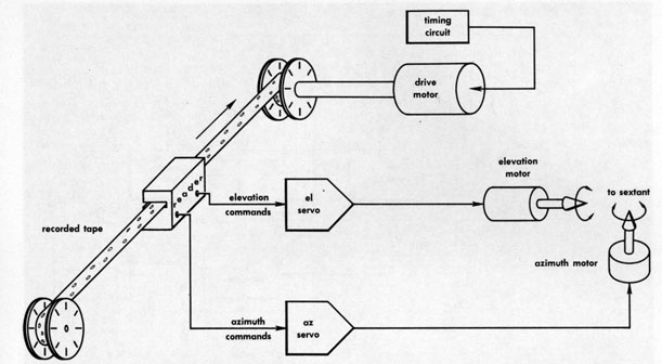 Figure 6D5.-Sextant positioning system. |
The position of the sextant is checked by a section called the STELLAR ERROR DETECTION CIRCUIT, which determines whether or not the star is centered in the telescope field. If the star is not centered in the field, an error signal is generated and processed to show the amount of sextant error. The error detection circuit is shown in block form in figure 6D6.
The elevation error signal from the direction resolver is fed to the pitch and roll resolver where it is compared to the tape signal. The output of the resolver is divided into two voltages-the pitch error signal and the roll error signal. It is not possible to obtain proportional control with this system because of the delay in signals getting through the circuits, and damping by the rate function. However, the system does tend to return the missile to the correct course as soon as possible without over-control oscillations.
TERRESTRIAL REFERENCE. Three characteristics of the earth's magnetic field that are useful for missile guidance are (1) lines of equal magnetic deviation, (2) lines of equal magnetic inclination, and (3) lines of equal magnetic intensity. Refinements of the
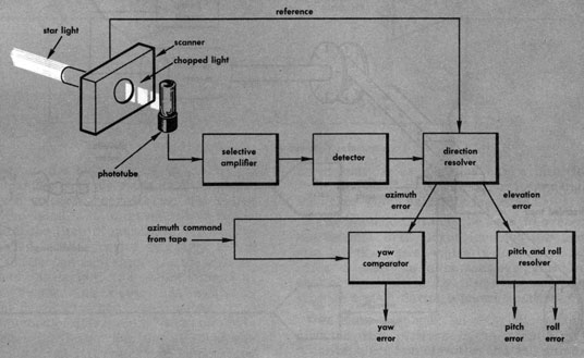 Figure 6D6.-Stellar error-detection circuit. |
The flux valve consists of primary and secondary windings on an iron core. The primary is supplied with a-c of a fixed voltage and frequency. When no external magnetic field is present, the device acts as a simple transformer; the frequency of the secondary voltage is the same as that of the input voltage. But when an external field is present, it will alternately add to and subtract from the field generated by the primary current, during successive half-cycles. As a result a second harmonic, at twice the input frequency, is superimposed on the output voltage. If the flux valve is properly aligned with the external magnetic field, the amplitude of the second harmonic voltage will be proportional to the strength of that field.
The output of the detector coil consists of the 400-cycle input frequency, combined with the 800-cycle harmonic that results from the action of the earth's magnetic field. This combined output is fed to a filter amplifier that amplifies the 800-cycle voltage, but eliminates the 400-cycle signal. The amplifier output is then fed to a frequency divider, which changes the 800-cycle signal back to a 400-cycle signal suitable for operating the missile control system. The amplitude of this signal will be proportional to the strength of the earth's magnetic field.
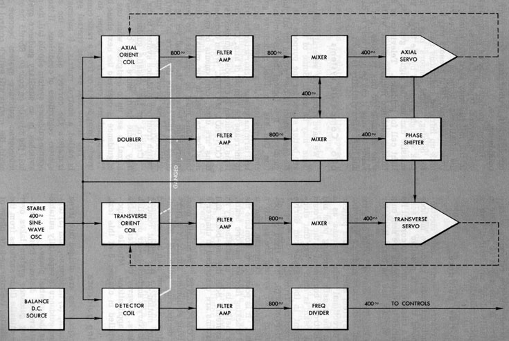 Figure 6D7. Magnetic system. |
| 124 | ||
| magnetic field. The flux valve output voltage can be compared with the reference voltage by a computer. In this way it is possible to guide the missile along any desired line of constant magnetic intensity. | ||
6D4. Beam-rider guidance
We have described some basic electromagnetic (radio and radar) guidance methods and have shown that it is possible to send commands to a missile in order to correct its trajectory. Since the commands are sent on a radio beam, why not use the beam itself for guidance?
PRINCIPLES. The answer to the question is the present beam rider guidance systems. Basically, the system uses the beam pattern of a highly directional radar antenna as a track between the missile launching point and the target. Electronic equipment on the ground modulates the beam in such a way that electronic equipment in the missile can derive guidance instructions from it.
FIXED COMPONENTS. The fixed components of a beam rider system are usually a target-tracking radar, a computer, and a guidance radar. It is possible to combine the guidance and tracking function into one beam. However, this method is not as satisfactory as a two-beam system. Both the one-beam and two-beam systems are described in chapter 8 of this book.
MISSILE COMPONENTS. The missile must contain receiving equipment suitable for picking up and deciphering guidance information. This information must then be converted to appropriate motion of the flight control surfaces. The Navy's surface-to-air missiles are beam riders. However, the system is also used in other applications. Missile components are detailed in chapter 8 of this text.
6D5. Homing guidance
Missile trajectories are divided into three phases (1) launch, (2) midcourse, and (3) terminal. Homing guidance is especially suitable for use during the terminal phase.
Homing guidance may be accomplished by one of several types of sensors. Radar sets in the missile may send out pulses, so that the missile may home on the echoes returning from the target. Heat sensors may be used to pick up infrared radiations that can be used for homing. Light sensors may be used to pick up light given off by the target, and the missile can use the signals generated by the light cell for guidance. Television is another homing guidance medium which, while otherwise suitable for this purpose, has limited value because it can be used only in daylight, and only when visibility is good.
6D6. Composite systems
We have shown how several guidance systems may be used. Some of these systems are better suited for one purpose than others. No one system is best suited for all phases of guidance. It is logical then to combine a system that has excellent midcourse guidance characteristics with a system that has excellent terminal guidance characteristics in order to increase the number of hits. Combined systems are known as composite guidance systems.
CONTROL MATRIX. When composite systems are used, components of each system must be carried in the missile. Obviously, the sections must be separated so there is no interaction between them and yet be located close to the circuits they are to control. In addition, some provision must be made to switch from one guidance system to the other.
Control of the missile guidance system may come from more than one source. A signal is set up to designate when one phase of guidance is over and the next phase begins. This signal may come from a tape, an electronic timing device, or from a radio command.
VELOCITY-DAMPING DOPPLER RADAR. One homing guidance system makes use of doppler principles. No doubt you have listened to a train whistle while the train was approaching rapidly. As the train moved past you, its whistle appeared to change in pitch (frequency). This same doppler effect is present in radar waves when there is relative motion between the target and the antenna of the radar.
Doppler homing equipment can be divided into two groups-FM-CW doppler systems, and pulse doppler systems. There are major differences in the circuitry of the two systems. In the FM-CW system, the frequency of an echo signal has a relationship to the speed of the target with respect to the receiving antenna. This echo signal can be converted into an indication of target velocity with respect to the missile.
The difference between the frequency of the transmitted signal and the frequency of the echo is due to the doppler effect. When the two signals are mixed in an electronic circuit, the circuit will develop a "beat" frequency equal to the difference between the two signal frequencies. The beat note developed in this manner will have a pitch that is proportional to the relative velocity between the target and the radar antenna. To eliminate the possibility of homing on objects other than the target, a band-pass filter (which will pass only a narrow band of frequencies) is inserted in the control circuit to eliminate interfering signals.
A pulse doppler system performs the same functions as an FM-CW system and, in addition, can select a target by its range. Like other pulsed radar systems, it has greater operating range for a given average power output than a CW system.
The guidance control signals are sent as a series of timed pulses. The receiving system in the missile must contain circuits that will match the transmitted pulses in both pulse timing and r-f cycles. The matching is accomplished in electronic circuitry known as the coherent pulse doppler system. In this system the transmissions are short pulses at a repetition frequency that can be continuously varied. Low-intensity power, which is used to obtain phase coherence between successive pulses, is generated by the stabilized local oscillator. A duplexer provides low-impedance paths to keep the oscillator energy in the desired circuits.